
Start with the decision, not the scanner
3D scanning serves several different purposes: documenting a part, reproducing it, comparing it with its design or measuring how much it has worn. Each goal calls for a different deliverable, and defining it at the start avoids paying for a more elaborate model than needed or, worse, receiving one that cannot be used for manufacturing.
Before scanning, answer one question: what decision will be made with the result? If it is manufacturing a spare part, you need a CAD model with functional dimensions. If it is deciding whether to repair or replace a mold, a comparison against a reference is enough.
From scan to CAD model
The process has four stages. First, the part is prepared: cleaning, stability and, if needed, targets or treatment of shiny surfaces. Then comes capture, where the scanner records millions of points on the surface. Next, processing: noise is removed, the captures are merged and a mesh is obtained. Finally, depending on the goal, the mesh is aligned with a reference CAD model or used as the basis for rebuilding the model.
At Fundimoldes we work with a HandySCAN 3D Silver, with a stated accuracy of 0.040 mm and a stated mesh resolution of 0.200 mm, on parts within a recommended range of 0.05 m to 4 m. The real feasibility of each project depends on the geometry, access and finish of the part.
Mesh, surfaces and parametric solid
| Deliverable | What it is | What it is for |
|---|---|---|
| Mesh (STL) | The captured surface, made of triangles | Documenting, comparing, 3D printing |
| Surfaces (IGES) | Surfaces fitted over the mesh | Organic shapes, a basis for machining |
| Parametric solid (STEP or native CAD) | Model rebuilt with dimensions and design intent | Manufacturing, modifying, producing drawings |
| Comparison report | Color map and measurements against a reference | Acceptance, wear diagnosis |
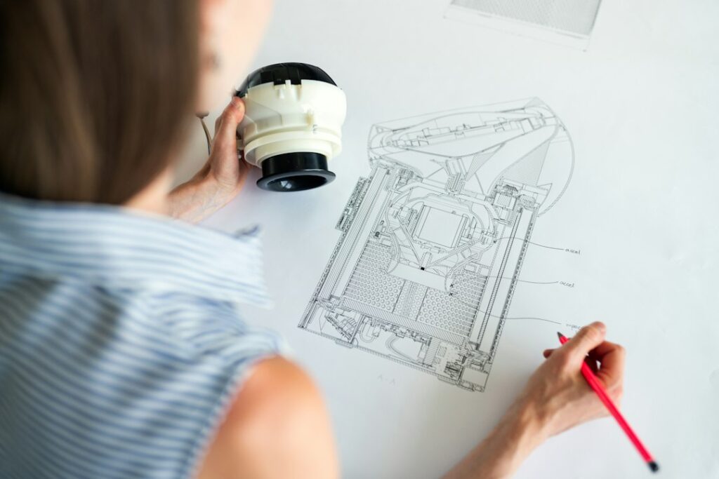
A mesh is not a drawing. To manufacture a spare part with fits, holes and tolerances, the model must be rebuilt with engineering judgment: deciding what is a perfect cylinder, which face is flat and which dimension is nominal, instead of copying the imperfections of the scanned part.
Limits worth knowing
The scanner records what it can see. Deep holes, internal cavities, narrow slots and very shiny or transparent surfaces are hard to capture and sometimes require preparation or complementary measurement. Threads and fine fits are usually defined by standard or drawing, not by scanning.
If a worn spare part is scanned and copied as is, the wear carries over to the new part. The rebuild should recover the nominal dimensions, ideally from a less used part or from the part that mates with it.
Inspection against CAD
When a design model does exist, scanning makes it possible to compare the real part against it. The result is a color map showing where the part sits above or below the nominal geometry and by how much. It is useful for approving the first parts from a new mold, finding the cause of a warped part or measuring cavity wear.
In maintenance, comparing successive scans of the same mold shows how wear progresses and helps plan the repair before rejected parts appear. For what to check, see the guide to mold component wear.
Checklist before scanning
☐ Document, reproduce or compare
☐ Required deliverable
☐ Target CAD software
☐ Required accuracy
☐ Size and weight
☐ Material and finish
☐ Wear condition
☐ Internal or hard-to-reach areas
☐ Partial drawings
☐ Mating parts
☐ Design CAD, if it exists
☐ Known critical dimensions
☐ Scanning on site or in our shop
☐ Part availability
☐ Required date
☐ Next step: manufacture or repair
Common questions.
Does the scan give me a drawing ready for manufacturing?
No. The scan delivers a mesh. To manufacture, a CAD model with nominal dimensions must be rebuilt and, if required, drawings produced. That engineering work is part of the reverse engineering scope.
Which formats can I receive?
We deliver STL, IGES, STEP or the CAD format agreed, plus comparison reports when the goal is inspection.
Can a mold that is in production be scanned?
Yes, during a maintenance stop. Scanning the mold and comparing it with its original condition or with earlier scans is an objective way to measure wear.
Need help with a similar project?
Share drawings, a 3D model or requirements with our technical team.